|
INSTALLING BIRDMAN'S FUSEBLOCKS PLEASE read these instructions before you install the fuseblocks. I guarantee they will answer most of your questions and make the install go faster!
1. Before doing anything, take a picture of both fuseblocks with your phone for reference in case you get confused later. 3. Pull the wires, unscrew the exisiting fuseblock, and screw in the new one. (I recommend doing only one at a time to minimize stray wires). Be sure to put the one marked "right side" on the right, and the one marked "left side" on the left...they are different!** (See note below for Right Hand Drive cars). Pay attention to which side is up. There is an arrow on the back which points up. The soldered "bus bars" are on the top row, not the bottom. It is never a bad idea to visually confirm that the bus bar pattern on the back of the Birdman Block match with the bus bar on the OEM block you are replacing. First, this is just a sanity check. Second, (and this happens often) one of the OEM blocks has been replaced by a previous owner with the incorrect block. The injected and carb blocks have a different bus bar pattern. You can make the wrong one work with some jumpers and this is what some owners have done, including the previous owner of my car. A melted fuseblock was replaced with an injected one from eBay and they did a work-around to make it work right. If you have ANY concern whatsoever about a new Birdman Block verses an OEM one, place them next to each other and take a picture of the back so I can see the bus bars. Then e-mail it to me. I'll tell you what is up. I DO NOT MIND!! I want to be sure you are 100% happy. If you aren't sure, don't be shy, just ask! IMPORTANT: be sure to install the new fuseblocks with the shorter screws that I supply with them. Birdman Fuseblocks are thinner than the stock ones, and if you use the longer stock screws, they stick out the back of the panel and can pinch a wire Ask me how I learned this. No joke! Be gentle with the fuse holders on the ends of the new fuseblock (#1 and #9 in the diagram above). They are not riveted down like the other fuseholders, but only held in place by the bus bar. The mounting screws for the whole block go through them. Once they are screwed down, the screw takes the place of the rivet used on the other fuseholders to hold them securely. 3. Now put the wires back on the right tabs, and put in AGC-type fuses. These fuses are available just about anywhere from the local hardware store to autozone and even places like Wal-mart. They are standard "glass fuses." Consult your owner's manual or the old fuseblocks for the proper fuse values. You may not be able to get the exact same fuse values as stock with the glass type fuses. The glass fuses have a slightly different set of values. Just use the closest value. For example, my OEM fuse blocks called for 16 Amps on many circuits and I'm using 15 Amps which is fine. They don't need to be exact, just fairly close so they will blow if you get an electrical problem but not blow if everything is working correctly. NOTE: Some circuits have two wires connected to them, and some only have one. In the case of the circuits with only one, just plug the wire right into the fuseblock. In the case of the circuits that have two wires, use the included "piggyback" splitters to connect two wires to one fuse. 4. That's it, you're done. This procedure should take no more than an hour, working at a leisurely pace. The only tools required are a screwdriver and a sharpie pen!
|
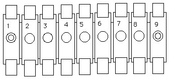 Number the wires according to this chart on each fuseblock before pulling them.
NOTE FOR GT4 OWNERS: **NOTE FOR RHD CAR
OWNERS: NOTE ABOUT FUSEBLOCK COVERS |
|
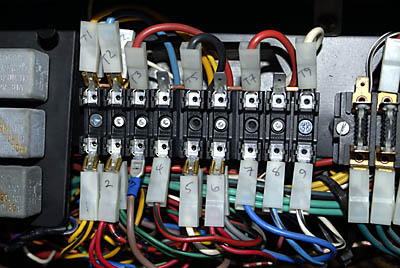
Here is a closeup of how I number my wires. The bottom row is 1, 2, 3 etc. and the top row is T1, T2, T3, etc.
Note T2 is melted from the original fuseblocks overheating. Also note the use of the splitters on the bottom row for the circuits that have two wires (1,2,6 and 7 on this example). Note that T4 and T8 have no wires connected. They get power through the bus bar on the back of the fuseblocks. |
|
|
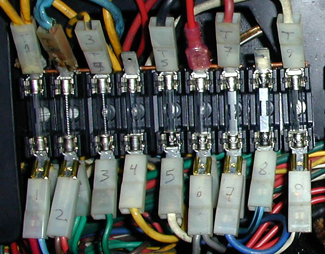
This shot of the left fuseblock of an injected car shows that T1 and T2 have multiple wires on the TOP not just the bottom. You can use the "piggyback" connectors here as well. Note the right fuseblock has not been changed yet. I like to do them one at a time to minimize confusion and rat's nest syndrome. |
|