Ferrari 308 CV joint and Drive shaft Seal replacement
By The Birdman
Lame printer-friendly layout
A special thanks to David Feinberg for this tutorial. He came over and walked me through it step by step so I know it was done right. And I’m just writing it up and taking all the credit. :-) If you are not capable of doing this job yourself, don't fret. Just call David and he will do it for you!
Background
A 308 has two drive shafts, (some call them “half-shafts”) that connect the differential to the rear wheels. Each drive shaft has two CV (constant velocity) joints that transfer the torque to the wheel but allow the drive shaft to flex slightly. This allows the suspension to move up and down on one end of the drive shaft while the other end is bolted straight into the transaxle. These are slightly different than a universal joint (“U joint”) because in addition to allowing the shaft to bend at the joint, they also allow a bit of in and out (telescoping) movement.
There are two reasons you might remove and service a drive shaft assembly:
1. One or more of the rubber boots on the CV joints has torn and the grease is leaking out. (This is bad! If the boot tears, the CV joint will fling all its grease on your engine and make a mess. It will also ruin the joint because it will run dry of lubricant.)
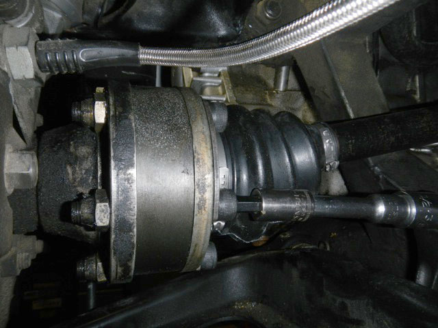
2. The drive shaft seal is leaking. This is the seal at the interface between the drive shaft and the transaxle. When this seal starts to leak, transmission oil sneaks out around it and gets flung by the rotating drive shaft on your engine and suspension. You are not only losing transaxle oil but also making a mess of your engine. The symptoms are easy to see: you have a “ring” of oil on your engine bay in a radius around the inner CV joint. A lot of times this looks like an oil leak from the cam cover dripping down on the engine below, but look carefully and you will see oil not just below but on the exhaust and back of the engine bay perfectly lined up with the inner CV joint. That’s where it gets thrown from.
This is a straightforward repair that just about anyone can handle. It’s a hell of a lot easier with a lift so you can get under the car easily, but it can be done on jack stands too. This procedure is going to outline the left hand side (drivers side in the USA) drive shaft and seal. This is the more difficult one. I’ll give a few tips on the passenger side, which is slightly different when it comes to the seal.
PART ONE: GET THE DRIVE SHAFT OUT
1. Remove the rear wheel and liner to you can gain access to the drive shaft. You do not need to remove the brakes, caliper or suspension in any way! Leave the car in neutral so you can rotate the rear wheels and access the drive shaft flange nuts easily.
2. There are six Allen head bolts holding the drive shaft to the hub flange and six more holding the other end to the transaxle flange. You need to get all 12 of these bolts out. This is the hardest part of this whole procedure because they are tight and it’s easy to strip the Allen head. The first thing to do is soak all the bolts and nuts in PB Blaster. (If you don’t have PB Blaster, go to NAPA and get some. It’s way better than WD-40.) Then go inside and have a beer. Actually several, because you are done for the day. The next morning, soak them again and go inside and eat breakfast. Beer optional. I want you to soak those bad boys 2-3 times over 24 hours before you even think about trying to crack them loose. Trust me on this part. If you rush it, you will strip one and then you will be swearing like a truck driver trying to cut the nuts off with a dremel. And let me tell you they are seriously hard steel and that sucks!
Once the nuts and bolt heads have soaked for 24 hours, you are going to crack them loose with a big long breaker bar, an 8mm allen socket and whichever extension allows you to reach those bolts. There are a couple things to keep in mind here. Those buggers are tight. Make sure you get the allen socket seated all the way in the bolt and hold it in there tightly while you crack it loose with the breaker bar.
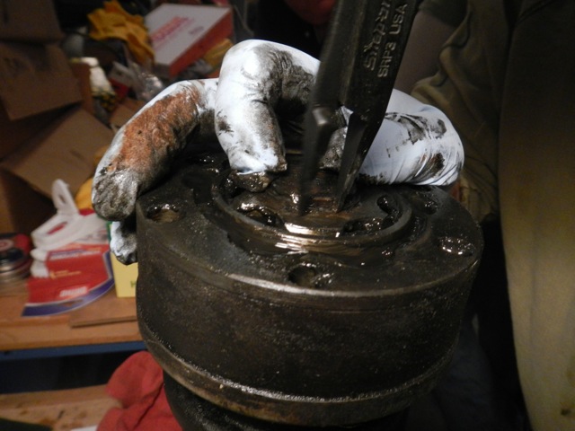
3. Keep the drive shaft from turning by putting a screwdriver into the slots of the brake rotor next to the brake caliper. The screwdriver will go above or below the brake caliper depending on whether you are loosening the bolts on the inner or outer hub. Don’t laugh, this is Ferrari factory procedure and works perfectly.
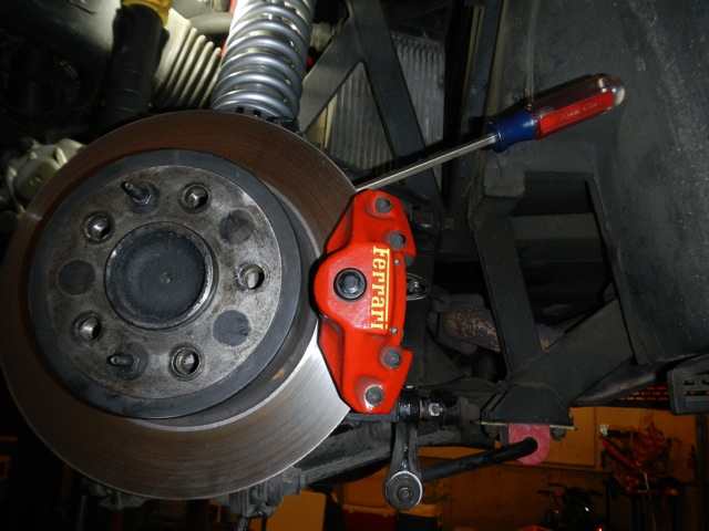
Factory method of keeping the axle from turning as you apply pressure to CV bolts!
Keep that socket square with the bolt and seated well. These bolts are tight!
4. Now that they are all loose, you can unscrew them. The nuts are semi-captive because they bump against the flange by design. So you don’t need to put a wrench on the nut to keep it from spinning. Once the bolt is nearly all the way unscrewed, you may have to grab the nut with your fingers to keep it from spinning.
5. I suggest keeping one bolt in each end of the drive shaft until you are nearly done so one end doesn’t fall off and hang down while you are doing the other end. This prevents damage to the collar on the CV joint where the rubber boot connects. Rotate the wheel between each nut removal to put the bolt/nut in a convenient location for the ratchet wrench.
6. Once all the bolts are out, you can remove the axle easily. Please note that the bolts on the inner CV joint have washers under them in addition to the half-moon shaped washers. That is to be sure the CV bolts don’t stick too far out the back and hit the bolts protruding from the transaxle! The washers go under the bolt heads, not the nuts!
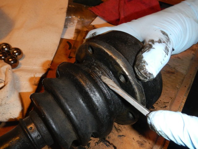
With the drive shaft on the bench, we can rebuild the CV joints easily. Do one joint at a time. Start by removing the clamp on the large opening of the boot.
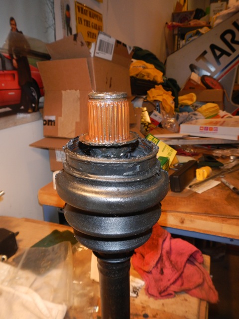
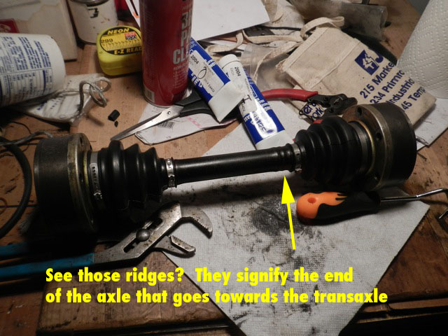
7. Now we will rebuild the CV joints. Bring the whole axle with both CV joints on it over to the bench. You will notice that one end of the axle has several “ribs” next to the rubber boot and the other end doesn’t. These ribs mark the “engine” side of the axle. We want to rebuild each CV joint and put it back on the same end of the axle, so when it’s reinstalled in the car, the parts are all aligned the way they once were, so the wear is consistent.
8. Pick a CV joint. Remove the clamp/tie that holds the larger end of the rubber boot to the CV joint.
A snap ring holds the CV joint to the splined end of the drive shaft.
Using snap ring pliers, expand the ring and pry ir out of the groove on the shaft. Be prepared to replace this ring because they often break.
9.
Put the axle on end on the bench and use snap ring pliers to remove the snap ring that holds the axle in the CV joint. You can clean and re-use this snap ring, but it’s a better idea to replace it. (If you buy David’s rebuild kits with top quality parts, I suggest you also get his far superior-to-stock metric snap rings too.)
With the CV joint off, you can see the location of the thrust washer at the base of the splines. Clean the splines thoroughly.
10. Pull the axle out of the joint. The rubber boot will stay on the axle because the other clamp (on the small end of the boot) is still attached.
11. Remove the thrust washer from inside the CV joint. It goes against the ridge on the axle. Please note that it is very slightly concave to provide pressure on the axle. Take note of how it comes out so you can put it back in correctly later.
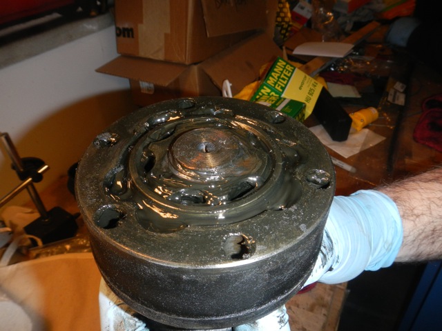
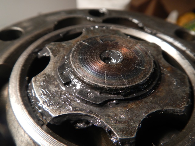
12. Rotate the inner assembly of the CV joint to get the balls out. Take note of the two surfaces of the inner CV joint part (the part which is splined for the shaft to go through). There is an inner and outer surface. Outer is flush, inner is raised slightly.
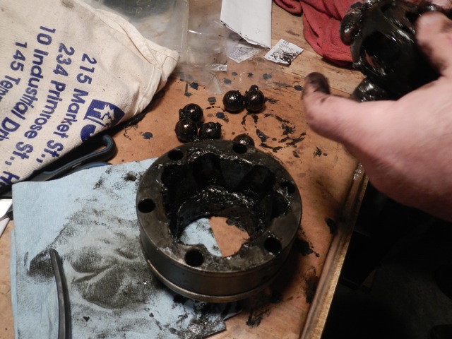
No way around it, this is a messy job. Take the guts out and clean everything squeeky clean with paper towels and brake cleaner.
13. Once the balls are out, the rest of the “guts” come out easily. Wipe all the old grease from all these parts, then clean with brake cleaner. Get it squeaky clean so you can inspect for wear. These things are damn tough. Unless there is significant wear on the balls, inside of the CV joint or inner “cage” you can just repack and go.
14. David’s rebuild kits will come with Oetiker clamps (the best clamps for this application), a 100 g tube of grease, and a new boot. Label the tube you are going to use for this CV joint so you know which one it is. (Label it inner or outer).
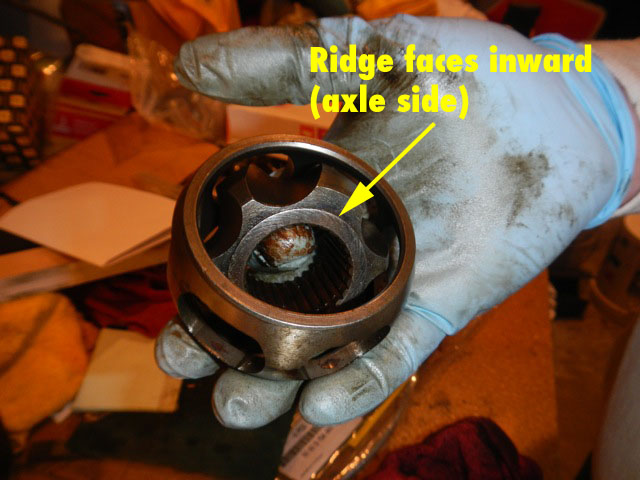
Clean inner parts of the CV joint. Pay attention to the ridge on the inner piece which needs to be oriented towards the thrust washer.
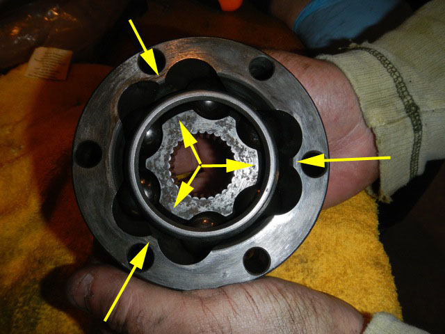
The CV joint will go together two different ways, but only one way works right when completed! Align the longer "flats" of the inner part with the shorter flats of the outer part as shown by the yellow arrows.
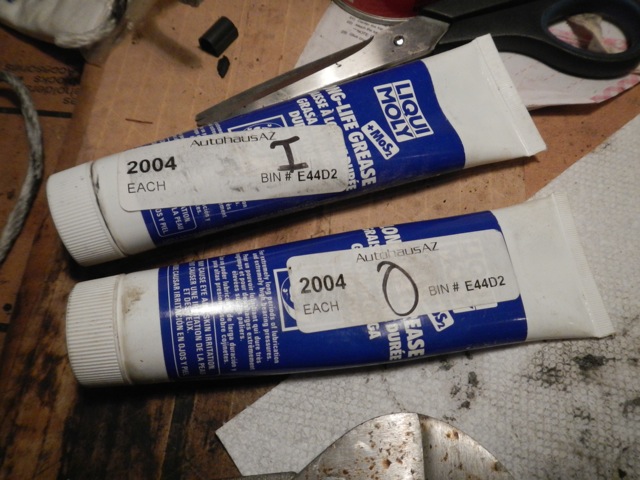
David's rebuild kits come with the correct grease. The entire tube goes into a CV joint. So label them I and O (for Inner and Outer!) so you keep track of how much lube goes into each joint.
15. Once all the guts are clean, re-assemble the CV joint dry. (Some people want you to pack it with grease and then re-assemble, but it’s much harder, much messier, and you get grease everywhere. It’s perfectly fine to assemble then squirt grease in. Once you have rolled 50 feet down the driveway, the grease has worked its way into all the balls.) See picture to show alignment of inner and outer pieces. It can go together a couple ways, but only one way is right. When it’s together, it should flex easily.
Remove the old boot from the axle.
16. Place the nice clean CV joint face down on the bench with the flange sticking up. Squirt about half the 100g tube of grease inside, around the inner rim of the joint.
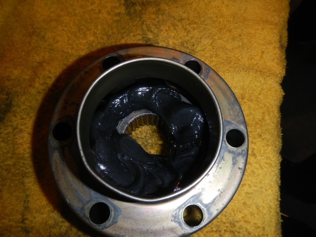
Place the CV face down on the bench and squirt about half a tube of grease around the circumference of the inside. Then drop the thrust washer in there centered on the alxe hole.
17. Drop the thrust washer in on top of the grease, centered on the hole. Concave should be down on the washer—peak should be up. This means that once the shaft goes on, it provides “springiness” to be compressed to get the snap ring on later.
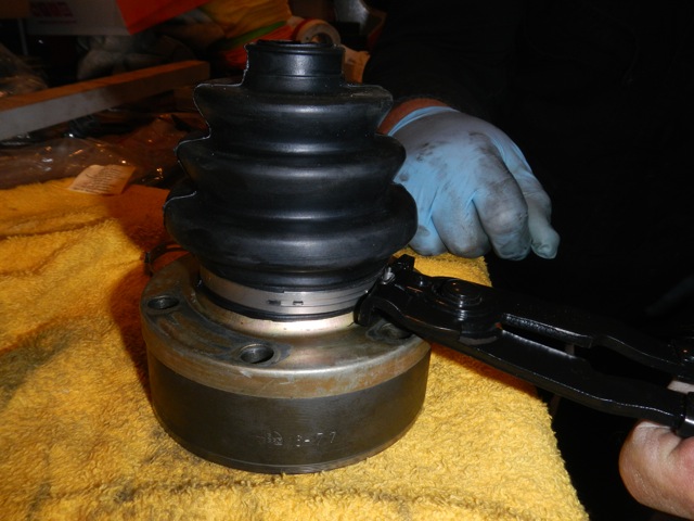
Boot installed and clamping the Oetiker clamp. Make sure the "nubbie" of the clamp doesn't interfere with a bolt hole!
18. Put the new boot on the CV joint while it’s sitting on the table. Yes, it’s easier to do it this way than to put the CV boot on the axle first. Trust me. Use a little silicone spray to lube up the edge of the CV boot so you can slip it over the CV flange.
19. Put the clamp on. If you don’t have an Oetiker clamp tool, you can use a set of flush cutting wire cutters. Make sure you put the clamped section between bolt holes so it won’t interfere with the bolts later.
20.
Now put a dab of CV grease inside the small end of the boot and wiggle the axle through it. Push the axle down, through the thrust washer sitting in there and into the splines of the inner CV joint. Now flip the whole axle over, put a socket of the right size on the inner CV joint and tap with a hammer to snug it up tight.

A nice new snap ring!
New snap ring in place.
21. Install the snap ring on the shaft. You might have to put a socket on there and tap gently to pop it into place on the groove at the end of the axle. The slightly concave thrust washer is what causes the need to need to tap it. The washer must flex a little to allow everything to seat and stay good and tight.
Do the other CV joint the same way.
22. Before you re-install the axle, squirt the rest of each of the tubes of grease into the other side of each CV joint. This is why you labeled them so you know you got the WHOLE 100g tube into each CV joint before re-assembly. No more, no less. (Too much is almost as bad as too little.)
The other half od the tube of grease goes in the other end of the CV joint. Wiggle the CV joint around to work it in. I suggest not doing this part until both CV joints have been rebuilt and you are ready to put it back into the car!
Voila! Ready to go back in the car!
When you re-install the axle, you need to torque the 12 allen bolts to 57 ft-lbs. Yes, that’s a LOT of torque for these allen head bolts. That’s why they were a bitch to remove. Ferrari wants them tight!
PART 2 – REPLACING THE DRIVE SHAFT SEAL IN THE DIFFERENTIAL
1. Buy the seal from David. He stocks a seal that is a double lipped version--way better than the Ferrari seal and half the price! Half the reason you are replacing this seal is because the Ferrari version is a single lip version that sucks!
2. Put the car in first gear to prevent the transaxle from turning.
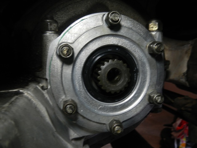
3. Use an impact wrench and 19mm socket to remove the big bolt from the center of the transaxle flange. (The flange on the transaxle that bolts up to the CV joint with six allen bolts).
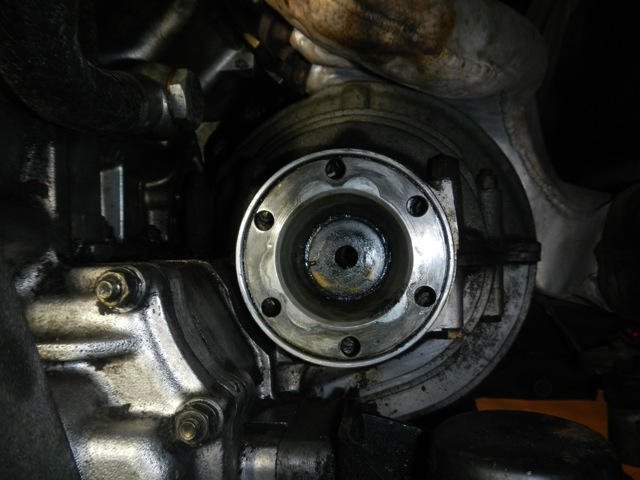
The bolt has been removed from the inner CV flange and the dimpled flat washer is still there.
4. Clean all the old silicone off this bolt and both washers. There are two washers. One is a big flat washer with a dimple to align it with the flange so it can’t rotate, and the other is just a lock washer. You should replace the lock washer because it’s probably flattened.
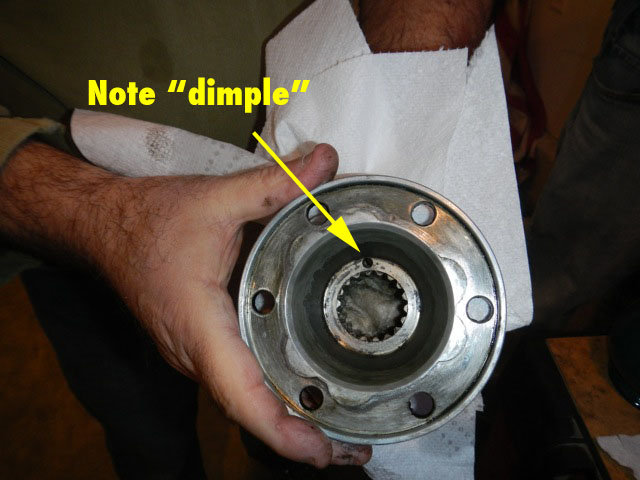
Once on the bench and cleaned up, you can see the small indentation for the flat washer to lock into with the tab on the washer. Note also splines inside this part which slides onto the output shaft of the differential.
5. Remove the six nuts (13 mm head) that hold the Differential Side Cover (Ferrari lingo) otherwise known as the Differential Seal Carrier (“DSC” works for both so we call it that for the rest of this tutorial) in place.
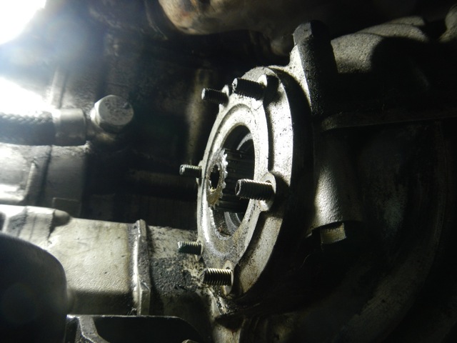
The six nuts have been removed from the differential seal carrier (DSC). This part holds the seal and we want to remove this part in order to seat the seal correctly. Some people try to skip this step and save a few minutes, but trust me, not worth it. The seal must be seated correctly to last.
6. Gently work the DSC off the engine. Be gentle!
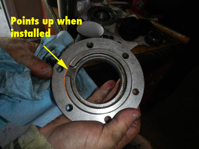
The DSC off the engine and all cleaned up. When you re-install, the slot inside points up.
7. Once it’s off, note mounting orientation. The “vent” slot on the back goes pointing up on re-assembly.
8.
Clean it and the transaxle surface to which it mates. Super clean. Don’t want any dripping later.
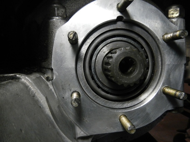
Squeeky clean and ready for the DSC to be re-mounted.
9.
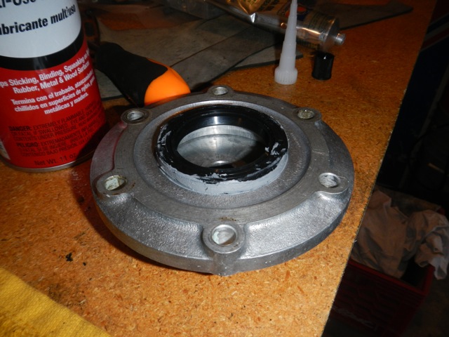
Note the orientation of the old seal (cup facing in) and push the old seal out of the DSC by hand. Toss the old seal. It’s toast.
Using Permatex 81182 as a "curable lubricant" eases the fitting of the seal, but will not remain "slippery" later. Note bearing race installed under the seal forms a backing so we can't push it in too far. See step 10 below.
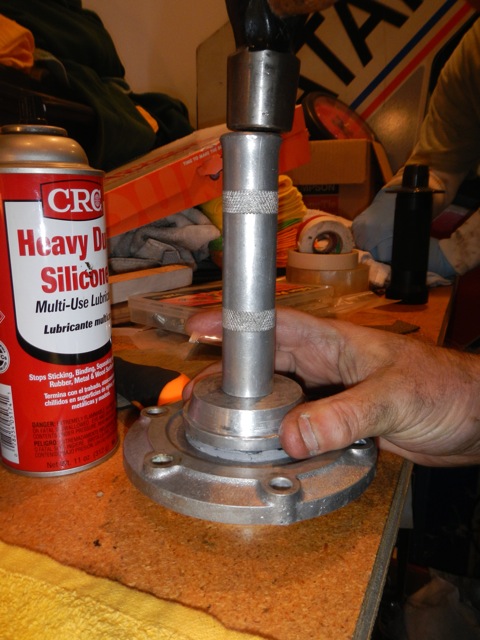
Another race installer and a few taps of a hammer push the seal right into place.
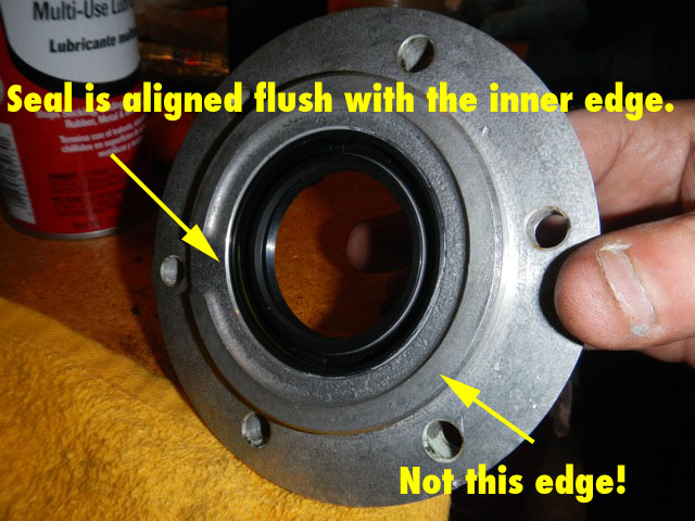
The inside of the DSC showing how the seal is correctly aligned with the indented section and not with the ridged part with the slot in it.
10. The new seal needs to be pushed in square, and seated to the right depth. Depth is very important! Too deep and it won’t seal. Too shallow and it rubs on the hub and gets ruined.Using a bearing race installer of the right size on the back of the DSC as a "stopper", then push the seal in from the front with another one so it’s flush with the indented surface on the back. You can use a little RTV to lube it so it goes in smoothly. You do not want to use lubricant like silicone, oil or grease on the outer edge of the seal because it will stay slippery and the seal might move later. If you use RTV (preferably gear oil compliant RTV such as Permatex 81182) as lube, 99% of it will get squeezed out, but what little remains will cure and not allow slippage. Keep in mind we are using the silicone as a “temporary lubricant” here, not a sealant. The rubber seal itself is nice and tight in this hole and doesn’t need a sealant.
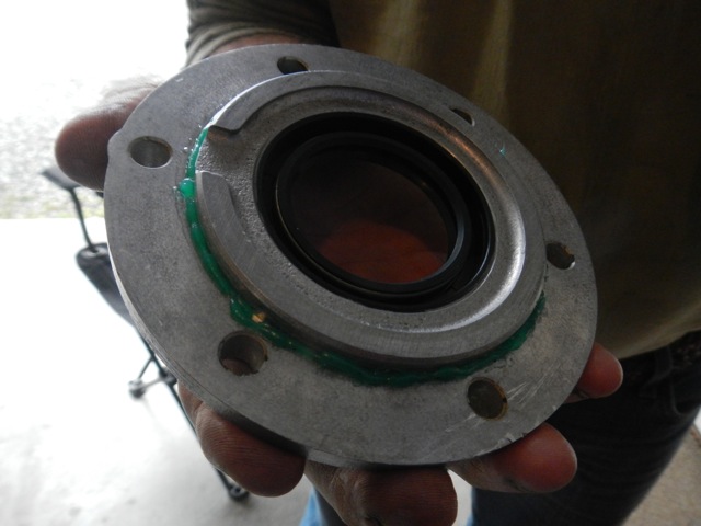
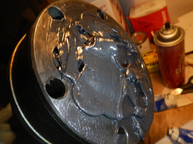
Sealant around the outside of the DSC and it's ready to be re-installed.
11. Coat the back of the DSC as seen in the picture with a tiny bit of sealant. (From David, a note about sealant: "We used Curil T. This sealant is a non-RTV product and very popular in the Porsche crowd. The only drawback perhaps, is that it's not the most readily available product. My next choice which is just as good is Loctite 574. Although very similar to 518, it has both higher temperature and strength ratings. Again, the only drawback perhaps, is that it's not the most readily available product. And lastly, Loctite 518. Not the best best possible product, but it will do the job and is readily available. I avoid all of the Hylomar products as past experiences have not been favorable. Perhaps this is unfair, as their products have likely changed.")
12. Bolt the DSC back onto the transaxle.
See, that was easy. It only took a few extra minutes to do it right.
13. There is an indent in the center of the inner hub where the big flat washer has a dimple to line up with it. This keeps the washer from spinning. Mark the outside of the flange with the location of this indent so you can find it later when it’s covered in RTV.
14. Now the very important part!! Coat the splines of the inner hub with gear oil RTV (Permatex 81182). Also coat the outer surface of the hub (where it mates with the seal) in a thin layer of non-drippy lubricant such as axle grease.
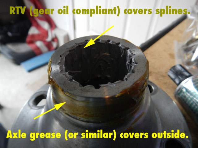
The RTV keeps transaxle oil from getting into the CV joint through the splines. The lube on the outside just keeps us from accidentally shifting the position of the seal in the DSC when we install this part.
15. Carefully slide the hub back onto the transaxle. The splines are tight. Getting them to match up takes a little patience.
16. When the hub slides in, the RTV will be pushed back out of the hub, but the splines are coated in RTV, and this is critical to keeping gear oil from leaking into the CV joint from the transaxle. Critical!
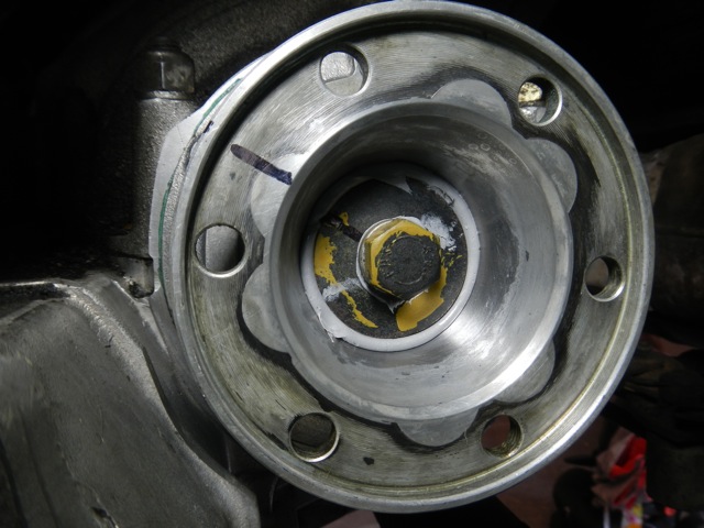
Now coat the base of the mounting bolt and flat washer with the same RTV as pictured. Screw it into the center of the hub keeping the dimple in the big flat washer aligned with the indent in the hub.
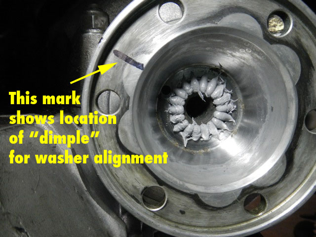
Once the the hub is back on, it should look like this. The output shaft of the diff pushes the RTV out of the splines (except for the thin layer that remains). The mark helps us align the washer once the dimple is covered in RTV.
17. Getting this bolt tightened down is tricky because the engine wants to turn. Put it in reverse (so when you are torqueing this bolt clockwise, the engine goes the right way if it turns) and either torque it down to 65 ft-lbs per the shop manual, or as David says “Just a quick hit with the impact wrench.” It just needs to be tight to keep the axle from coming out. However, the bolt doesn't carry much load itself as the splines take all the torque of the axle.
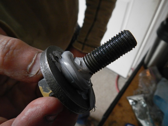
Washer and bolt with RTV. We are still using the Permatex 81182.
Nice! No gear oil is getting through that!
Go have a beer, because this wants to cure 24 hours.
18. RTV will goop out around the flat washer. This is good! We are sealing this thing so gear oil can’t get into the CV joint and ruin the grease and/or sneak around the rubber boot.
19. Allow the RTV to dry a full 24 hours before going any further. Drink beer. You are done for today.
20. When the RTV is dry, re-install the axle. Torque CV bolts to 57 ft-lbs.
21. Replace the liner and wheel.
22.
Drive.
Notes for the passenger (right) side. There is no “DSC” on the passenger side. You remove the axle, then pull the seal out with a hook and press the new one directly into the transaxle.
If you need the parts kits in this tutorial or you just want to hire a professional to do the job, contact David Feinberg at: ferrariservice@comcast.net
Last update: 4/3/12